Embedded Insight Archives
 |
 |
 |
 |
 |
/*------------------------------------------------------------------*\
Embedded Insight
The Monthly Newsletter for Embedded Systems Professionals
Published by Base2 Software Design, Inc.
    http://www.base2software.com
    mailto:info@base2software.com
June, 2002
\*------------------------------------------------------------------*/
Contents- Hardware CODECs
- Base2, Digital Audio, and You
- Programmer's Corner - Linear Interpolation
Hardware CODECs
A hardware CODEC is an IC that performs COding and DECoding of audio. While it would be theoretically possible to do this mostly in software, CODECs relieve the software from some hard-to-meet timing requirements and provide some nifty features to boot.
A Little Background
In order to record and playback digital audio, conversions must take place between the digital and analog domains. This is accomplished through an analog to digital converter (ADC) and a digital to analog converter (DAC). (See Diagram 1.)
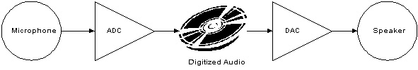
Diagram 1: Simple ADC/DAC system
To record a waveform, samples are read from the ADC at equal time intervals. To playback the waveform, samples are written to the DAC, again at equal time intervals. The rate at which samples are read/written is called the sampling rate. For example, the standard sampling rate for CDs is 44,100 samples per second (44.1 kSa/s).
The Software Problem
Let's assume that we're trying to build a software system to playback audio at 44.1 kSa/s. This means that the DAC must be written every 22.7 µs. This rate must be maintained precisely; human ears are very sensitive to variations in sound, so if the DAC isn't written every 22.7 µs exactly, our ears will be able to tell.
This is relatively difficult to guarantee in software, especially since the software probably has many duties to perform other than just babysitting the DAC. And it's also harder to do when the sampling rates are high (44.1, 48, or even 96 kSa/s). So how do we guarantee our sampling rate? One way is to use a hardware CODEC.
A Hardware Solution
The diagram below shows a simple microprocessor and CODEC setup. Most CODECs interface to a microprocessor through a synchronous serial interface. A couple of popular interfaces are I2S (developed by Philips http://www.semiconductors.philips.com/acrobat/various/I2SBUS.pdf) and SPI (developed by Motorola). In addition to the audio serial channel, there is often a control serial channel implemented with an I2C or an SPI serial port. This gives the software access to extra features such as bass/treble control, pre-amp control, audio serial data format, and many others.
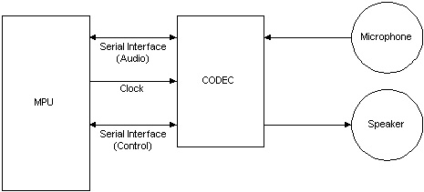
Diagram 2: MPU/CODEC system
To playback audio, the software continuously writes to the CODEC. To record audio, the software continuously reads from the CODEC. The most important difference between this setup and the raw ADC/DAC setup is that now the software can read and write in bursts. Synchronous serial interfaces usually feature buffered I/O so that the software can read or write 2, 4, 8 or more samples at a time thus giving the software an easier time constraint to work within.
For example, suppose that we have a system where the synchronous serial interface has a 4-position FIFO, and we want to play audio at a sampling rate of 44.1 kSa/s. After we fill the FIFO, we have from 22.7 to 90.7 µs to refill the FIFO with 1 sample to 4 samples, respectively. That's a much easier requirement to meet than having to service a DAC every 22.7 µs exactly.
It's a Tradeoff
The decision to use or not to use a hardware CODEC is still a tradeoff between performance and cost. If you are designing a toy with a sampling rate of 8 kSa/s and cost constraints are paramount, you may not need nor want a CODEC. However, when designing a higher-end system, a hardware CODEC provides many features and benefits that are well worth the price.
Base2, Digital Audio, and You
Are you thinking of incorporating digital audio into your next device? Do you need help selecting an audio algorithm or designing a digital audio player or recorder? Base2 Software Design is your source for digital audio expertise. With years of experience in digital audio, embedded systems software, and audio theory and practice, we can help you make your product sound its very best. For more information on what we can do for you, please contact Michael Miu at 510/745-7773 or e-mail him at mailto:mmiu@base2software.com?Subject=Digital%20Audio.
Programmer's Corner - Linear Interpolation
The problem: you've got a waveform sampled at 11.025 kSa/s, but the digital output is set to 44.1 kSa/s. What can you do? One thing you can try is playing each sample 4 times. If you try this, though, you'll find that this sounds terrible. An easy solution is linear interpolation.
Interpolation is filling in the blanks between the known data points. There are many techniques, but linear interpolation is the easiest. It assumes that the relationship between each contiguous point is linear. In the case of our example, the following code would do the trick.
/*---------------------------------------------------------------------------*\
    Name:   unsigned int Interpolate11to44( short * outBuf, short * inBuf,
            int numSamples );
    Description:
         This routine interpolates a buffer of 11.025 kSa/s audio to a
         buffer of 44.1 kSa/s audio or indeed any sampling conversion where
         you need a 4:1 ratio. It works with 16-bit sample sizes.
     Arguments:
         short * outBuf  -   The 44.1 kHz output buffer. Must be
                             4X bigger than inBuf.
         short * inBuf   -   The 11.025 kHz input buffer.
         int  numSamples -   The number of samples to interpolate.
     Returns:
         unsigned int    -    The number of samples in outBuf.
\*---------------------------------------------------------------------------*/
short prevSample = 0;
unsigned int
Interpolate11to44( short * outBuf, short * inBuf, int numSamples )
{
    long i, j;
    for ( i = 0; i < numSamples; i++ ) {
        for ( j = 0; j < 4; j++ )
            outBuf[i*4 + j] = prevSample + ((long) inBuf[i] - (long) prevSample) *
                              j / 4;

        prevSample = inBuf[i];
    }
    return numSamples * 4;
}
The global prevSample
should be initialized once per session. The routine Interpolate11to44()
can then be called multiple times in succession to interpolate a long
piece of audio.
|
|
Base2 Software Design, Inc. Phone: 510/745-7773 |
If you know anyone who would like to receive this informative newsletter, please forward this to them. They can sign up by sending an e-mail to mailto:info@base2software.com?Subject=Subscribe.
If this newsletter was sent to you in error or if you'd like to unsubscribe to our newsletter, simply send an e-mail to mailto:info@base2software.com?Subject=Unsubscribe.
You may use the contents of Embedded Insight in whole or in part if you include the following complete copyright notice and live links:
Copyright 2002, Base2 Software Design, Inc.
http://www.base2software.com.
mailto:info@base2software.com.
© 2002-2009, base2 software design, inc.